Moment Calculation for a Continuous Beam
How to Use The Free Beam Calculator
The ClearCalcs beam calculator allows the user to input the geometry and loading of a beam for analysis in a few simple steps. It then determines bending moment, shear and deflection diagrams, and maximum demands using a powerful finite element analysis engine.
Signing up for a ClearCalcs account will unlock further advanced features for design and analysis of beams and a variety of other structural elements. ClearCalcs enables design in steel, concrete and timber, according to Australian, US and EU Standards.
The sheet is divided into three main sections:
- 'Key Properties', where the user inputs the geometry of their chosen section and the beam supports.
- 'Loads', where the use can input distributed, point and applied moment loads,
- 'Summary', which displays the key outputs and diagrams.
A 'Comments' section is also included for the user to leave any specific design notes. Clicking on any of the input/property labels gives a descriptive reference explanation.
1. Input Key Properties
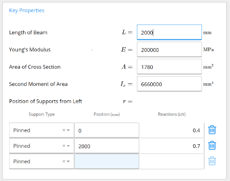
The properties of the beam and section are specified by typing directly into the input fields.
Length of Beam is the total including all spans of the beam, in mm or ft.
Young's Modulus is set to a default value of 200,000 MPa or 29000 ksi for structural steel, but can be edited by the user.
Area of the Cross-Section is specific to the beam section selected, and is defaulted to the values for a common steel beam.
Second Moment of Area (or Moment of Inertia) is also specific to the beam section selected, and again defaulted to the properties of a common steel beam.
The properties E, A, and Ix for other beam sections can be obtained from the ClearCalcs section properties library. Alternately, you can create your own custom section using our free moment of inertia calculator.
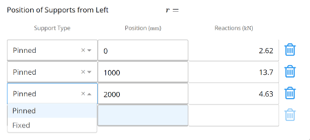
Position of Supports from Left allow the user to input any number of supports, and specify their position along the length of the beam. The support type can either be pinned (fixed in translation, free in rotation) or fixed (fixed in both translation and rotation) and is selected from the drop-down menu. A minimum of one fixed support, or two pinned supports are required.
The beam calculator also allows cantilever spans at each end, as the position of the first support does not have to be equal to 0mm and the last support position does not have to be equal to the length of the beam.
The reactions at each of the supports are automatically updated as supports are added, changed or deleted, based on the specified loading.
2. Input Loads
The calculator supports a variety of different loading types which can be applied in combination. Each load can be named by the user.
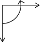
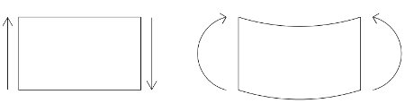
The sign convention used for loading is (positive values shown):
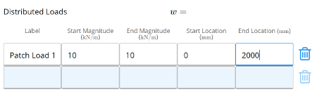
Distributed Loads are specified in units of force per unit length, kN/m or plf, along the beam, and can be applied between any two points. Two different types can be applied in the calculator:
Uniform Loads have a constant magnitude along the length of application. Therefore, the start and end magnitudes specified by the user must be the same.
Linear Loads have a varying magnitude along the length of application. The different start and end magnitudes must be specified by the user, and they can be used to represent triangular or trapezoidal loads.
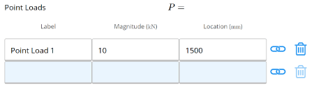
Point Loads are specified in units of force, kN or kip, and area applied at discrete points along the beam. For example, these can represent reactions from other members connecting to the beam. The user inputs the name, magnitude and location from the left of the beam.
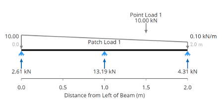
The example diagram below, from the summary section, shows a two-span continuous beam with a linear distributed patch load and point load.
3. Calculation Summary Outputs
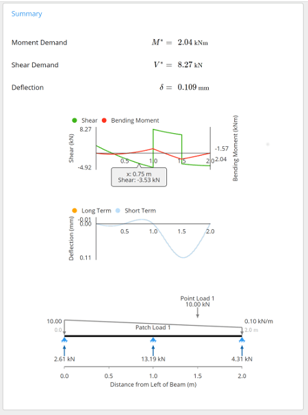
Once the loading and geometry have been specified, the calculator automatically uses the ClearCalcs finite element analysis engine to determine the moments, shear forces and deflections. The maximum values of each are output as 'Moment Demand', 'Shear Demand' and 'Deflection', along with the diagrams along the length of the beam.
Positive values imply a downward deflection and negative values imply an upward deflection. The sign convention used in the shear force and bending moment diagrams is (positive values shown):
Using the cursor to hover over any point on the bending moment, shear force or deflection diagrams gives the specific values at that location along the beam. The example below shows the outputs for a two-span continuous beam with a linear distributed patch load and point load.
hutchinsonwhentry1987.blogspot.com
Source: https://clearcalcs.com/freetools/beam-analysis
0 Response to "Moment Calculation for a Continuous Beam"
Post a Comment